


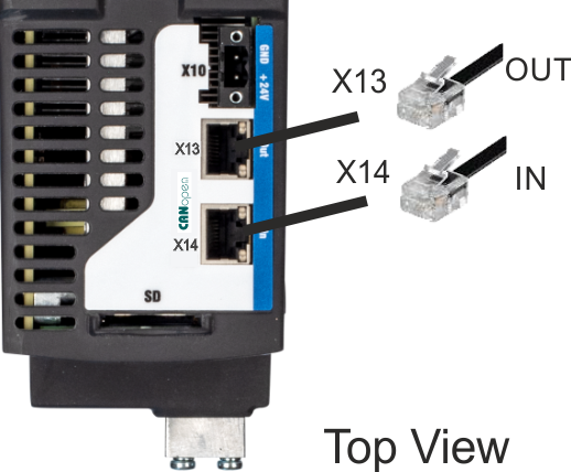
CAN-Bus Interface connector X13/X14
AKD2G drives with connectivity option C can be connected to a CAN-Bus by using two 6-pin RJ25 connectors X13/X14.
|
|
|
Pin |
Signal | Description |
|---|---|---|
|
1 |
Termination |
Internal Termination Resistor |
|
2 |
Shield |
Chassis |
|
3 |
CAN_high |
CAN bus high signal |
|
4 |
CAN_low |
CAN bus low signal |
|
5 |
CAN_GND |
CAN bus ground |
|
6 |
Termination |
Internal Termination Resistor |
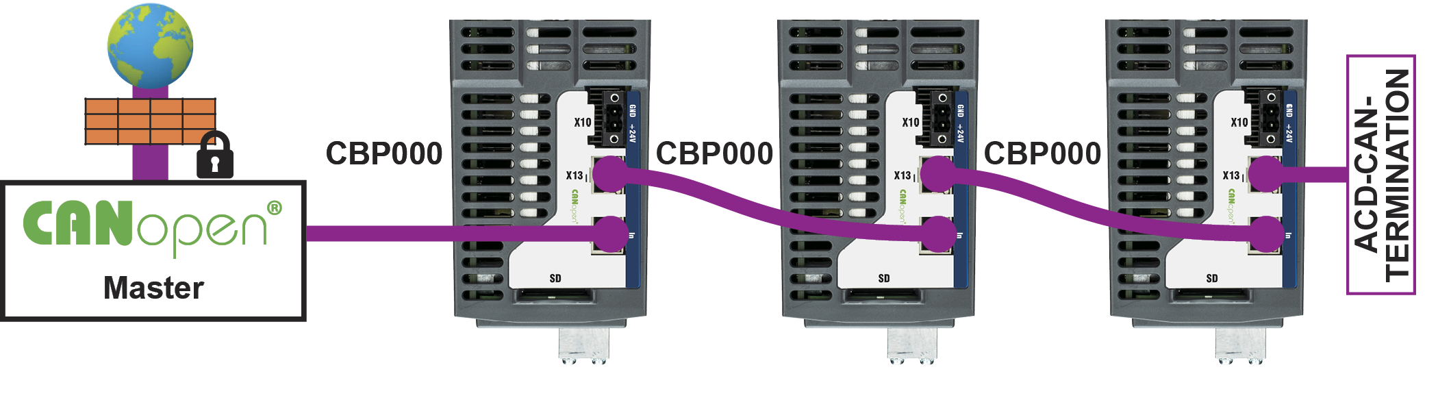
CAN-Bus Topology
We recommend the use of Kollmorgen CBP000 cables.
Cable requirements
To meet ISO 11898, a bus cable with a characteristic impedance of 120 Ω should be used. The maximum usable cable length for reliable communication decreases with increasing transmission speed.
As a guide, you can use the following values measured by Kollmorgen; however, these values are not assured limits:
- Characteristic impedance: 100–120 Ω
- Cable capacitance max.: 60 nF / 1000 m
- Lead loop resistance: 159.8 Ω / 1000 m
|
Transmission Rate (kBaud) |
1000 |
500 |
250 |
125 |
|
Maximum Cable Length (m) |
25 |
100 |
250 |
500 |
Lower cable capacitance (max. 30 nF / 1000 m) and lower lead resistance (loop resistance,
115 Ω / 1000 m) allow larger distances. The characteristic impedance 150 ± 5 Ω requires terminating resistor 150 ± 5 Ω.
Communication profile
For CANopen communication profile description refer to the manual "AKD2G CAN-Bus Communication".
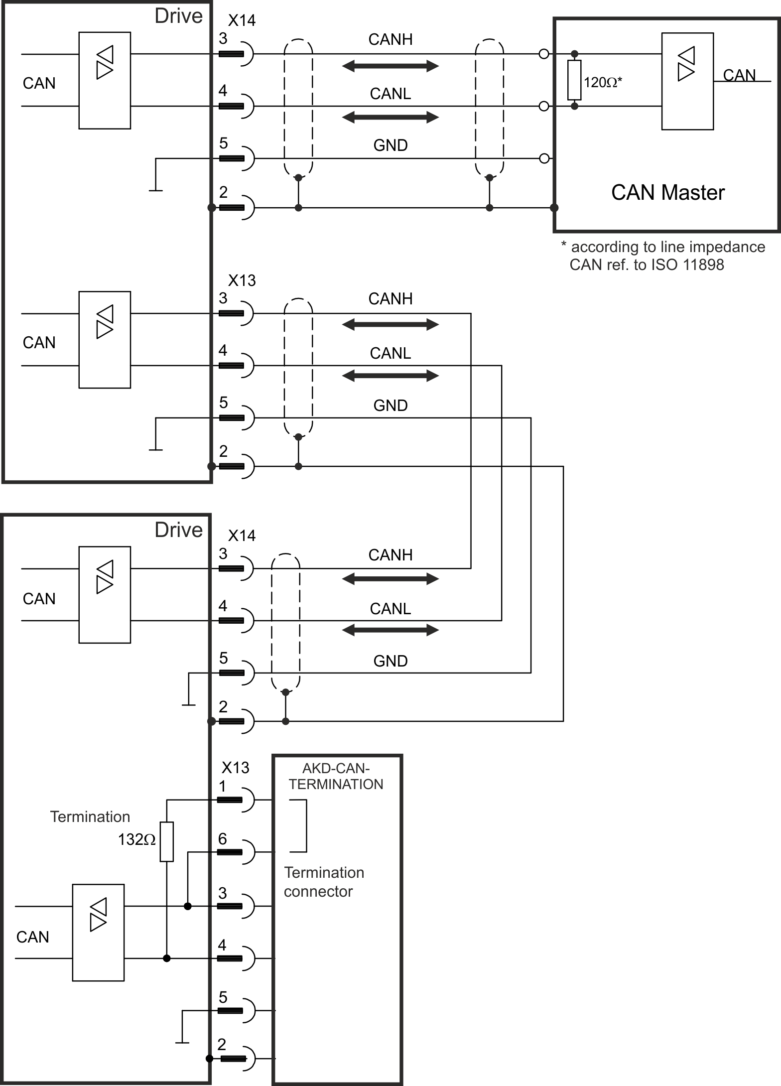
CAN-Bus Wiring
Baud rate for CAN-Bus
The transmission rate can be set by using the parameter CANBUS.BAUD in WorkBench.
|
Baud rate [kBit/s] |
CANBUS.BAUD |
|---|---|
|
125 |
125 (default) |
|
250 |
250 |
|
500 |
500 |
|
1000 |
1000 |
With a fix baud rate, the drive sends the boot up message with the baud rate saved in the drive's non volatile memory after a power cycle.
Node Address for CAN-Bus
The node address can be set by using parameter CANBUS.NODEID in WorkBench.

|
After changing the node address, you must turn off the 24 V auxiliary supply for the drive and then turn it on again. |
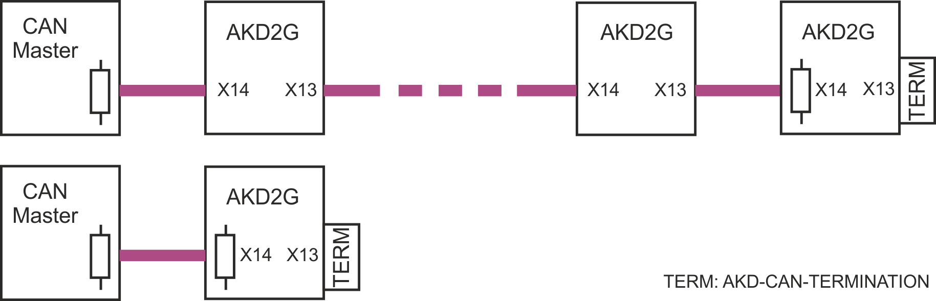
CAN-Bus Termination
The last bus device on both ends of the CAN-Bus system must have termination resistors. The AKD2G has built-in 132 Ω resistors that can be activated by connecting pins 1 and 6. An optional termination plug is available for AKD2G (AKD-CAN-TERMINATION). The optional termination plug is an RJ25 connector with an enclosed wire jumper between pins 1&6. The termination plug should be inserted into the X13 connector of the last drive in the CAN network.
|
|
Remove the termination connector if the AKD2G is not the last CAN-Bus device and use X13 for connecting the next CAN node. |


